Home
/ 555 Timer Schematic : Two Led Flasher By 555 Timer _ The 555 timer is a chip that can be us…
555 Timer Schematic : Two Led Flasher By 555 Timer _ The 555 timer is a chip that can be us…
555 Timer Schematic : Two Led Flasher By 555 Timer _ The 555 timer is a chip that can be us…. 555 datasheet 555 duty cycle 555 metronome 555 reset function 555 time delay relay inverted 555 timer pulse generator. We have 10 images about schematic diagram 555 timer manual, schematic diagram 555 timer instruction manuals, schematic diagram 555 timer user manuals, service manual, schematic diagram 555 timer pdf download, user guides. Here, with the help of the 555 timer ic, we are eliminating the need of manually switching on or off the device. Once this switch is pushed, the circuit pulls its output to a. In the inner configuration of this ic flip flop and comparator circuit are present which helps the circuit to behave like a toggle switch.
The standard 555 timer ic is made of 2 diodes. In this circuit, we will connect the 555 timer to be in astable mode. The 555 timer delay before turn on circuit we will build is shown below. 555 datasheet 555 duty cycle 555 metronome 555 reset function 555 time delay relay inverted 555 timer pulse generator. We have a large collection of simple and advanced projects using 555 timer ic.
Homemade Inverter Schematic from electronoobs.com 555 timer circuits simple electronic circuits. Also, 555 timer is used to generate an oscillating pulse. As discussed in the above section, the ic is in its standard monostable mode. Ic 555 timer is a one of. This pin connects to the negative side of the battery. We connect a 100μf capacitor to the positive voltage supply and then to pin 2. Working modes of 555 timer ic. If you want to know all the pinout of the 555 timer, what each pin is and what each pin does, see 555 timer pinout.
555 timer is an industrial standard ic existing from early days of ic.
Derivatives provide two or four timing circuits in one package.it was commercialized in 1972 by signetics. Figure 2 shows the basic 555 timer monostable circuit. This circuit uses very basic components like 555 timer and 4017 counter. Lm555 timer 1 features 3 description the lm555 is a highly stable device for generating 1• direct replacement for se555/ne555 accurate time delays or oscillation. The time intervals can be used for keeping a relay controlled load on or activated for the desired amount of time and an automatic switch off once the delay period. The output voltage from the chip is around 1.5 v lower than vcc when high and around 0 v when low. In this circuit, we will connect the 555 timer to be in astable mode. Ic 555 timer is a one of. Being an integral part of electronics project, 555 timer ic is very often used in simple to complex electronics projects. Circuits into the ever increasing ranks of timer users. Referring to the timing diagram in figure 3, a low voltage pulse applied to the trigger input (pin 2) causes the output voltage at pin 3 to go from low to high. The 555 timer ic is an integrated circuit (chip) used in a variety of timer, delay, pulse generation, and oscillator applications. The output of the voltage divider circuit is connected to pin 6 of the ic.
If a 10uf timing capacitor is used, calculate the value of the resistor required to produce a minimum output time delay of 500ms. This pin connects to the negative side of the battery. In the circuit, pin 2 and pin 6 are connected, and pins 4 and 8 are also connected. A collection of 555 circuits using the 555 timer as an astable oscillator with different duty cycles. A monostable 555 timer is required to produce a time delay within a circuit.
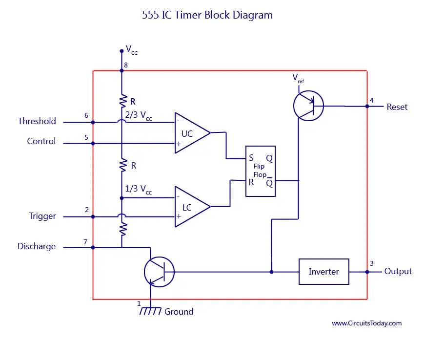
555 Timer Ic Block Diagram Working Pin Out Configuration Data Sheet from www.circuitstoday.com The output of the voltage divider circuit is connected to pin 6 of the ic. Let us discuss in detail about this circuit. A monostable 555 timer is required to produce a time delay within a circuit. 555 timer helpers schematic the addition of a capacitor to the trigger will not work for short output pulses as there is also a short delay in the recovery of the trigger terminal voltage. In this video, we will learn to make a latching circuit using a 555 timer ic. The circuits explained here are 10 best small timer circuits using the versatile chip ic 555, which generates predetermined time intervals in response to momentary input triggers. To understand the basic concept of the timer let' s first examine the timer in block form as in figure 1. The 555 ic timer circuit above shows a very straightforward design where the ic 555 forms the central controlling part of the circuit.
The working modes of a 555 timer are astable, bistable, and monostable.
Referring to the timing diagram in figure 3, a low voltage pulse applied to the trigger input (pin 2) causes the output voltage at pin 3 to go from low to high. There are simple circuits for beginners and advanced engineers. Additional • timing from microseconds through hours terminals are provided for triggering or resetting if • operates in both astable and monostable modes desired. A monostable 555 timer is required to produce a time delay within a circuit. Once this switch is pushed, the circuit pulls its output to a. This tutorial provides sample circuits to set up a 555 timer in monostable, astable, and bistable modes as well as an in depth discussion of how the 555 timer works and how to choose components to use with it. Let us discuss in detail about this circuit. These on off intervals can be adjusted by varying the 555 timer output and number of counter outputs. 555 timer helpers schematic the addition of a capacitor to the trigger will not work for short output pulses as there is also a short delay in the recovery of the trigger terminal voltage. We connect a 100μf capacitor to the positive voltage supply and then to pin 2. The values of r1 and c1 determine how long the output will remain high. In 2017, it was said over a billion 555 timers are produced. 555 ic timer block diagram 555 ic timer block diagram.
We have 10 images about schematic diagram 555 timer manual, schematic diagram 555 timer instruction manuals, schematic diagram 555 timer user manuals, service manual, schematic diagram 555 timer pdf download, user guides. 555 timer helpers schematic the addition of a capacitor to the trigger will not work for short output pulses as there is also a short delay in the recovery of the trigger terminal voltage. Lm555 timer 1 features 3 description the lm555 is a highly stable device for generating 1• direct replacement for se555/ne555 accurate time delays or oscillation. Each mode of operation indicates a circuit diagram and its output. The 555 timer can be obtained very cheaply from pretty much any electronic retailer.
Schematic Of The Original Bat Chaser Ultrasonic Generator Built Around Download Scientific Diagram from www.researchgate.net The working modes of a 555 timer are astable, bistable, and monostable. The output voltage from the chip is around 1.5 v lower than vcc when high and around 0 v when low. If you want to know all the pinout of the 555 timer, what each pin is and what each pin does, see 555 timer pinout. Being an integral part of electronics project, 555 timer ic is very often used in simple to complex electronics projects. These on off intervals can be adjusted by varying the 555 timer output and number of counter outputs. Once this switch is pushed, the circuit pulls its output to a. This circuit uses very basic components like 555 timer and 4017 counter. 555 timer circuits (133) browse through a total of 133 555 timer circuits and projects including the timer's datasheet.
Once this switch is pushed, the circuit pulls its output to a.
555 ic timer block diagram 555 ic timer block diagram. Let us discuss in detail about this circuit. We have 10 images about schematic diagram 555 timer manual, schematic diagram 555 timer instruction manuals, schematic diagram 555 timer user manuals, service manual, schematic diagram 555 timer pdf download, user guides. Here, with the help of the 555 timer ic, we are eliminating the need of manually switching on or off the device. With this information you will learn how how the 555 works and will have the experience to build some of the circuits below. A collection of 555 circuits using the 555 timer as an astable oscillator with different duty cycles. 555 timer is an industrial standard ic existing from early days of ic. We connect a 100μf capacitor to the positive voltage supply and then to pin 2. There are simple circuits for beginners and advanced engineers. In this category, we have handpicked some really useful 555 timer circuits which will be interesting to electronics engineering students and hobbyists alike. The time intervals can be used for keeping a relay controlled load on or activated for the desired amount of time and an automatic switch off once the delay period. We have a large collection of simple and advanced projects using 555 timer ic. This circuit uses very basic components like 555 timer and 4017 counter.

